PlanetPast
EN

Technology · Physics · History

How Railway Signalling Works

One Train, One Empty Track

On 28 October 2026 a high-speed train ran into the back of another that had stopped near Urda, on Spain's Madrid–Seville line; regional authorities said at least 68 people were killed, and an independent commission is investigating. This film explains the fundamentals the investigation will turn on: why steel wheels on steel rails need kilometres to stop; how time-interval working failed at Clayton Tunnel in 1861 and the block system replaced it; how William Robinson's track circuit of 1872 detects trains and fails safe; how interlocking and the Armagh disaster of 1889 shaped the rules; why red, yellow and green signals are spaced by braking distance; how cab signalling such as Germany's LZB and Japan's automatic train control took over at high speed; what the Santiago de Compostela derailment of 2013 showed about gaps in protection; and how Europe's ETCS and moving block work.

Interactive 3D film11 min1861 to 2030Published 29 October 2026

Watch the interactive filmRead in ไทย

Prologue

Technology · History

One train, one empty track

How railway signalling keeps trains apart.

On 28 October 2026, near Urda in central Spain, a high-speed train ran into the back of another that had stopped, according to first reports. Officials said at least sixty-four people were killed, and later sixty-eight.

Spain's transport minister said the second train had been allowed to continue although the system showed the track ahead occupied, a decision he called inexplicable. An independent commission will establish the cause.

How does a railway know that the track ahead of a train is empty? That is the oldest problem on the railway. This film explains how signalling solves it, and where it can still fail.

km 118
on the Madrid–Seville high-speed line
Near Urda, Toledo province
146
passengers on the stopped train
397
passengers on the train behind
Two trains, one track
  • Both trains were running Madrid to Seville
  • The front train had stopped on the line
  • The system showed the track occupied, the minister said
  • The cause is under investigation
What is known so far
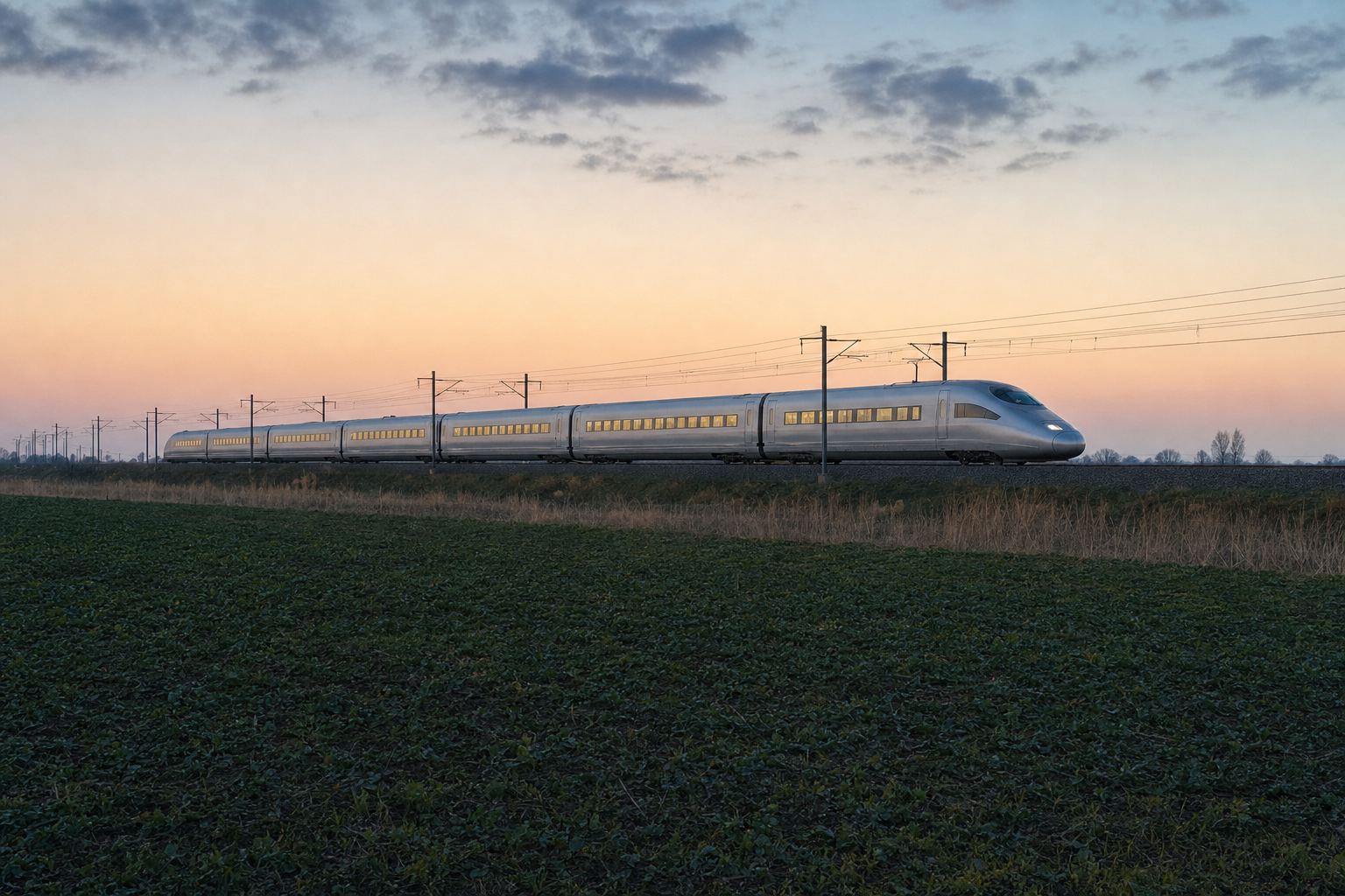
A train standing on open track Spain's high-speed lines use a different track gauge from the older network, so the two are physically separate railways. AI-generated still.
  • Why trains cannot stop by sight
  • Blocks, track circuits and signals
  • Cab signalling and train protection
  • Gaps, and moving block
In this film
Prologue

The collision near Urda

ABC News, 28 October 2026: two Madrid-to-Seville trains, run by Renfe and Iryo, collided near kilometre 118 (reported times range from about 8:30 to 8:54 a.m.) close to Urda, Toledo province. A Castilla-La Mancha spokesperson said at least 68 people were killed (some first reports gave 64); the Iryo train carried 146 passengers and the Renfe train 397, according to the Transport Ministry. Authorities said the Renfe train probably struck the Iryo train from behind. CBS News, citing TVE: the trains were heading in the same direction and one ran into the tail of the other. Demócrata, citing Europa Press: the Atocha control centre let the second train resume although the system showed red, the track being occupied by the Iryo train; Railway News and Demócrata: Transport Minister Óscar Puente called that authorisation “inexplicable”; the Guardia Civil is working with the railway accident investigation commission (CIAF), and no definitive conclusions have been released.

The figures above are the first official figures of 28 October 2026 and may change.

The 3D railway is a teaching model: distances are to scale where numbers are given, but trains, signals and cables are drawn larger so they can be seen.

Sources: ABC News (28 Oct 2026): train collision on a high-speed line in Spain kills at least 68; CBS News (28 Oct 2026): high-speed train accident in Spain near Urda; Railway News (Oct 2026): Spain train crash near Urda, Renfe and Iryo, what is known; Demócrata, citing Europa Press (Oct 2026): the Guardia Civil questions the Adif operator who authorised the AVE before the Urda accident
Chapter I · Too heavy to stop

Chapter I

Too heavy to stop

Steel on steel grips very little.

Start with physics. A car stops because rubber grips asphalt. Steel wheels on steel rails grip far less: the friction between them is about a third of a tyre's, or less.

That low friction is why trains are so efficient, and why they are so hard to stop. A car braking hard from a hundred kilometres an hour needs about forty metres.

A high-speed train braking from three hundred needs from just over three to four and a half kilometres. Pick a speed and brake both.

Tyre on dry asphalt0.7–0.8
Steel wheel on rail0.1–0.3
Rail with fallen leaves~0.05
Grip, as a friction coefficient
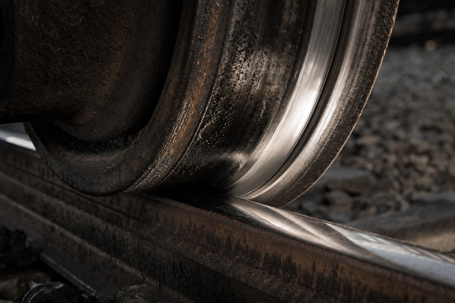
Steel on steel The patch where one wheel touches the rail is about the size of a small coin. AI-generated still.
d=v22ad = \frac{v^2}{2a}
vv
speed when braking starts
aa
deceleration: about 8 m/s² for a car, about 1 m/s² for a train
Stopping distance at steady braking
~40 m
car from 100 km/h
3.2–4.5 km
high-speed train from 300 km/h
Emergency stops, dry and level
Chapter I · Too heavy to stop

Why trains need kilometres

Railway News: the friction coefficient is about 0.7–0.8 for rubber tyres on dry asphalt and about 0.1–0.3 for steel wheels on steel rails, falling to about 0.05 with leaf contamination. Indicative emergency stopping distances on dry, level track: about 40 m for a car from 100 km/h, and 3,200–4,500 m for a TGV or ICE high-speed train from 300 km/h. Passenger trains decelerate at roughly 0.8–1.3 m/s² in an emergency, against 8–10 m/s² for a car with ABS. Wikipedia, railway signalling: low wheel–rail friction means braking distance “can be many kilometers”.

Try it: the model brakes both at constant deceleration (8 m/s² for the car, 1 m/s² for the train). Real braking varies with weather, gradient and the train.

The 3D railway is a teaching model: distances are to scale where numbers are given, but trains, signals and cables are drawn larger so they can be seen.

Sources: Railway News: train braking distance, how long does a train take to stop?; Wikipedia: railway signalling

At three hundred kilometres an hour a train covers eighty-three metres every second, and braking hard it needs more than a minute to come to rest.

So by the time a driver can see something on the line, it is far too late. A train cannot be driven by sight. Something has to tell the driver, kilometres ahead, whether the track is clear.

Every signalling system is an answer to one question: how do we know that the track in front of this train is empty?

t=va=83 m/s1 m/s2≈83 st = \frac{v}{a} = \frac{83\ \mathrm{m/s}}{1\ \mathrm{m/s^2}} \approx 83\ \mathrm{s}
vv
300 km/h written as metres per second
Time to stop
~3.5 km
travelled while braking, in this simple model
In those 83 seconds
Nothing to see in time High-speed lines are fenced along their whole length and have no level crossings, so there is nothing to meet on the track. AI-generated still.
How do we know that the track ahead is empty?The question behind every signal
Chapter I · Too heavy to stop

Too late to see

300 km/h is 83.3 m/s. At a steady deceleration of 1 m/s² a train needs v/a ≈ 83 s and v²/2a ≈ 3.5 km to stop, inside the 3.2–4.5 km range Railway News gives for high-speed trains. Wikipedia, railway signalling: trains run on fixed rails and their weight and inertia make stopping quickly difficult, so the line must be known to be clear well beyond what a driver can see.

The 3D railway is a teaching model: distances are to scale where numbers are given, but trains, signals and cables are drawn larger so they can be seen.

Sources: Railway News: train braking distance, how long does a train take to stop?; Wikipedia: railway signalling

Chapter II · Time and the telegraph

Chapter II

Time and the telegraph

A stopwatch cannot see a train.

The first answer was time. Under time-interval working, a railway policeman let a train go only if the one before had left a set number of minutes earlier.

But time says nothing about where a train is. On 25 August 1861, three trains left Brighton, in England, within seven minutes, though the rule required five between each.

Inside Clayton Tunnel, the second train, halted by a red flag, was hit by the third. Twenty-three people died. A stopwatch cannot see a train that has stopped. Try stopping the first train.

  • Train passes: start the watch
  • Under the set minutes: show danger
  • After it: let the next one go
The time-interval rule
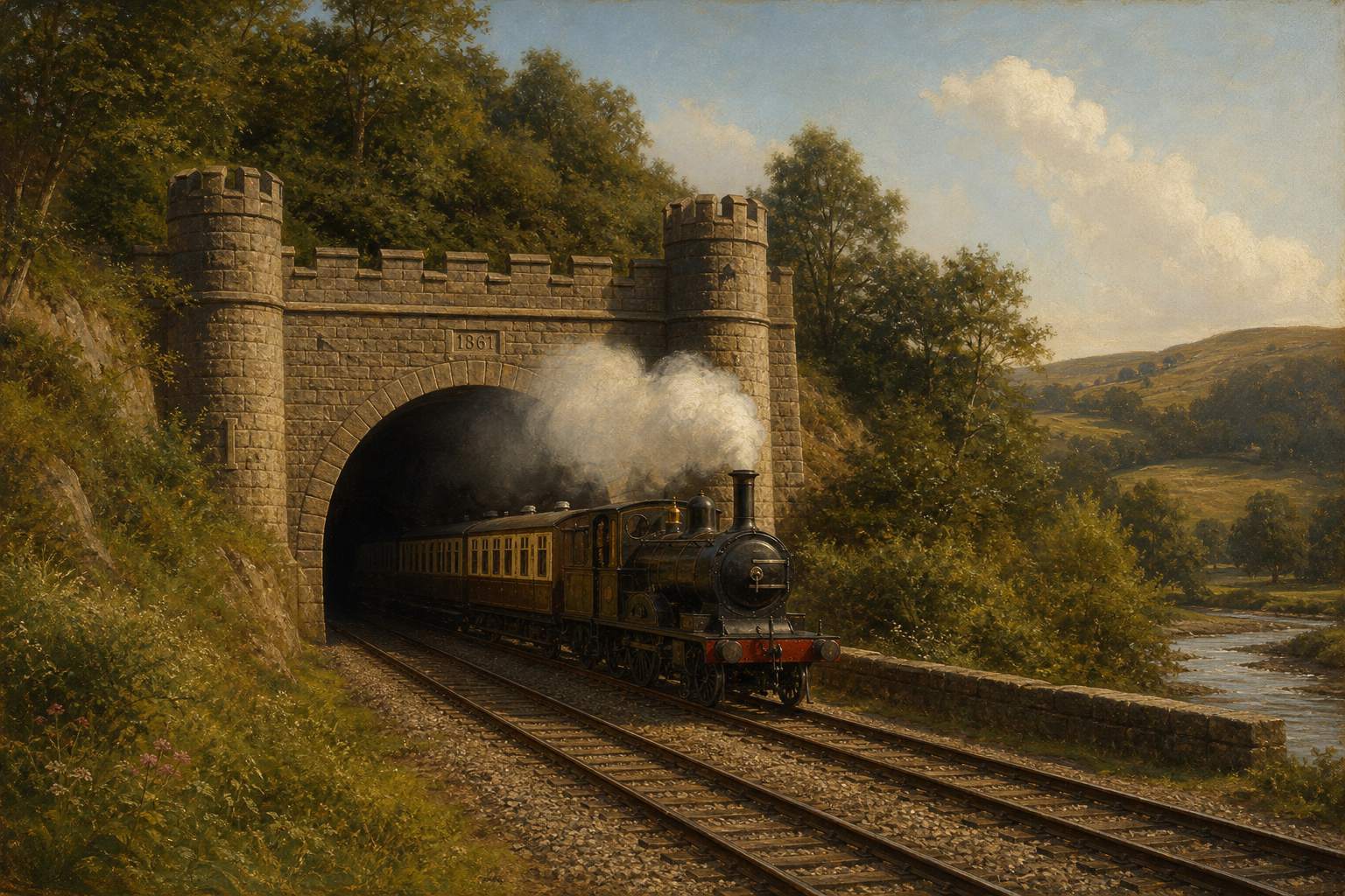
Clayton Tunnel, Sussex A steam train leaves a castellated tunnel portal, in the style of the 1860s. AI-generated still.
  1. 8:28 First train leaves
  2. 8:31 Second train, 3 minutes later
  3. 8:35 Third train, 4 minutes later
Brighton, Sunday 25 August 1861
23
killed
176
injured, of 589 passengers
Clayton Tunnel crash
Chapter II · Time and the telegraph

Clayton Tunnel, 1861

Wikipedia, railway signalling: under time interval working, watchmen signalled whether a train had passed more or less than a set number of minutes before. Wikipedia, Clayton Tunnel rail crash: on Sunday 25 August 1861 three northbound trains left Brighton at 8:28, 8:31 and 8:35, breaking the line’s five-minute rule. A signal at the south end failed to return to danger; a red flag stopped the second train inside the tunnel, and after a misunderstood telegraph exchange the third train was let in and struck it. 23 people were killed and 176 injured of 589 passengers. The disaster encouraged the adoption of the block system in place of time-interval working.

Try it: under the time rule the second train leaves on the clock, whether or not the first one has stopped.

The 3D railway is a teaching model: distances are to scale where numbers are given, but trains, signals and cables are drawn larger so they can be seen.

Sources: Wikipedia: railway signalling; Wikipedia: Clayton Tunnel rail crash

The answer was to divide the line by space, not time. The track is cut into sections called blocks, and the rule is simple: only one train in a block at a time.

Signalmen at each end of a block talked by electric telegraph, with bell codes. A train could enter only after the next box sent back line clear: the train before had left the block.

This absolute block system spread through Britain in the 1850s and 1860s. But it still relied on people never making a mistake.

1 train
per block, whatever the clock says
The block rule
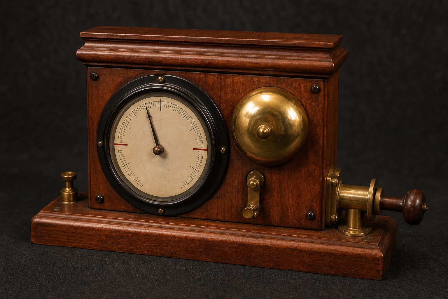
A block instrument A wooden telegraph instrument with a needle dial and a bell, in the style of the Victorian era. AI-generated still.
  • Ask ahead: is the block clear?
  • Answer by bell: line clear
  • Only then: signal off, train enters
A block, step by step
  1. 1832 Lineside flags and balls seen from afar
  2. 1841 Telegraph lets orders run ahead of trains
  3. 1850s–60s Absolute block spreads in Britain
Signals by wire
Chapter II · Time and the telegraph

Space, not time

Wikipedia, railway signalling: wayside signalling dates to 1832, with elevated flags or balls; the telegraph, from 1841, let train orders be sent ahead of trains. In the absolute block system, telegraph bell signals confirmed that a train had passed and a block was clear before another was admitted. It came into use gradually during the 1850s and 1860s and was made mandatory in the UK by the Regulation of Railways Act 1889.

On screen: a train may enter the next block only when the signal box ahead has sent back “line clear”.

The 3D railway is a teaching model: distances are to scale where numbers are given, but trains, signals and cables are drawn larger so they can be seen.

Sources: Wikipedia: railway signalling

Chapter III · Failing safe

Chapter III

Failing safe

A fault must look like a train.

To stop depending on people, the line had to detect trains by itself. In 1872 the American engineer William Robinson patented the closed track circuit.

A small current runs along the two rails to a relay, an electric switch, at the far end of the block. While the block is empty, the current holds the relay closed, and the signal can show clear.

A train's steel wheels and axle join the rails together. The current takes that short cut instead, the relay lets go, and the signal falls to danger.

The clever part is what happens when something breaks. A broken rail, a cut wire or a power failure also makes the relay let go. The fault looks like a train, so the signal goes red. Try it.

  1. 1864 Sykes uses a track circuit at Brixton, London
  2. 1870 Robinson’s open circuit, Pennsylvania
  3. 1872 Closed circuit: the first fail-safe automatic system
Robinson’s track circuit
1.5–12 V
typical DC across the rails
A gentle current
  • Axle joins the rails
  • Current bypasses the relay
  • Relay drops: signal at danger
Block occupied
  • Broken rail
  • Cut wire
  • Power failure
  • Rust or leaves can still fool it: a wrong-side failure
Faults that turn it red
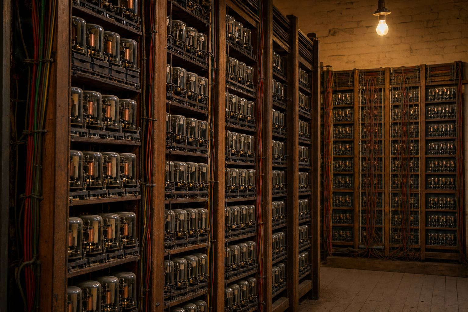
A room full of relays Relay rooms like this still run parts of many networks, decades after they were wired. AI-generated still.
Chapter III · Failing safe

A circuit that fails safe

Wikipedia, track circuit: low-voltage power, typically 1.5 to 12 V DC, is applied to the rails at one end of a block and a relay is connected across them at the other. A train’s wheels and axles short the rails, the relay drops and the block shows occupied. A broken rail or wire, a power failure or a short also de-energise the relay, so most faults look like an occupied track; some, such as rust, sand or leaves insulating the wheels, can still give a false clear (a wrong-side failure). Sykes used track circuiting at Brixton in 1864; Robinson’s 1870 open circuit could fail unsafely, and his closed circuit of 1872 was the first fail-safe automatic system. Wikipedia, William Robinson: patent for the closed track circuit, 1872.

Try it: put a train in the block, break a rail, or clear it, and watch the relay and the signal.

The 3D railway is a teaching model: distances are to scale where numbers are given, but trains, signals and cables are drawn larger so they can be seen.

Sources: Wikipedia: track circuit; Wikipedia: William Robinson (inventor)

Signals must also agree with the points, the movable rails that switch a train from one track to another. Interlocking locks the two together: a signal cannot clear for a route unless the points are set and locked for it.

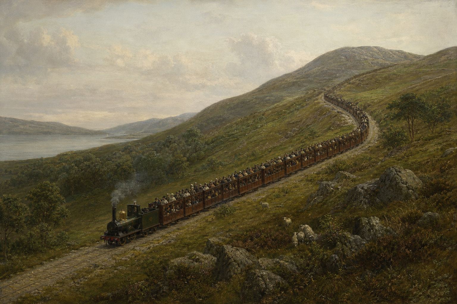
Brakes mattered too. In 1889 near Armagh, in Ireland, a crowded excursion train was split on a slope it could not climb, and its rear half rolled back into the train behind. Eighty people were killed.

A new law then let regulators require block working, interlocking, and automatic brakes that apply themselves if a train breaks apart. Try clearing the signal with the points set the wrong way.

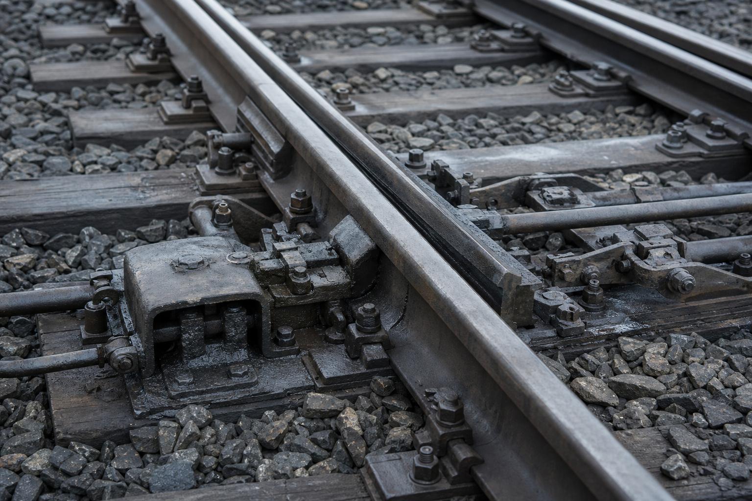
Points, and their lock Movable switch blades steer a train from one track to another. AI-generated still.
  • A clear signal over unlocked points
  • Two routes that cross, cleared at once
  • Moving points under a train
What interlocking forbids
An excursion train, 1889 About 940 passengers set out for the seaside at Warrenpoint. AI-generated still.
80
killed
260
injured
Armagh, 12 June 1889
Block
working on passenger lines
Interlocking
of points and signals
Brakes
automatic and continuous
Regulation of Railways Act 1889
Chapter III · Failing safe

Armagh, 1889

Wikipedia, railway signalling: mechanical interlocking was introduced to stop signalmen operating appliances in an unsafe sequence; relay interlockings began around the 1930s and electronic ones since the mid-1980s. Wikipedia, Armagh rail disaster: on 12 June 1889 a Sunday-school excursion train of about 940 passengers stalled on a steep incline; the crew divided it, and the rear section, whose non-automatic vacuum brakes could not hold it once uncoupled, ran back into a following train. 80 people were killed and 260 injured; roughly a third of all casualties were children. Armagh is today in Northern Ireland. The Regulation of Railways Act 1889, passed within about two months, let the Board of Trade require block working, interlocking of points and signals, and automatic continuous brakes on passenger lines.

Try it: set the points to the side track and try to clear the main-line signal; the lock refuses.

The 3D railway is a teaching model: distances are to scale where numbers are given, but trains, signals and cables are drawn larger so they can be seen.

Sources: Wikipedia: railway signalling; Wikipedia: Armagh rail disaster

Chapter IV · Red, yellow, green

Chapter IV

Red, yellow, green

Each signal watches the block ahead.

With track circuits, blocks can protect themselves. This is automatic block signalling: each signal watches the block in front of it.

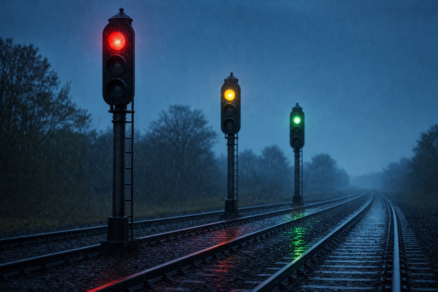
A red signal means the block ahead is occupied. Yellow means the next signal is red, so begin braking now. Green means at least two blocks ahead are clear.

The yellow is there because of braking distance: the driver must be warned at least one full braking distance before the red. Stop the front train and watch the one behind.

1 block
one track circuit, one signal at its entrance
Track circuit to signal
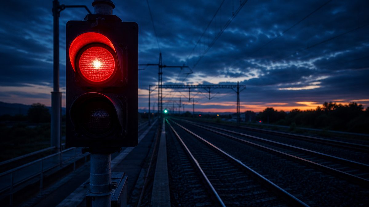
Red, yellow, green Some railways add a double yellow, a second warning, when one braking distance is not enough. AI-generated still.
  • Red: the block ahead is occupied, stop
  • Yellow: next signal red, brake
  • Green: two or more blocks clear
Three aspects
yellow to red  ≥  braking distance\text{yellow to red} \;\geq\; \text{braking distance}
The rule that spaces the signals
red
at the block it occupies
yellow
one block further back
Behind a stopped train
Chapter IV · Red, yellow, green

Signals that set themselves

Wikipedia, railway signalling: track circuits allowed manual block working such as absolute block to be replaced with automatic block signalling, in which fixed blocks typically start and end at signals. Colour-light signals show the same aspects by day and night and need less maintenance than semaphores. In a common three-aspect scheme, red is stop, yellow warns that the next signal is at red, and green shows that the next two blocks are clear; the yellow must stand at least one braking distance before the red.

Try it: stop the front train; the signals behind it turn red and yellow on their own, and the following train brakes.

The 3D railway is a teaching model: distances are to scale where numbers are given, but trains, signals and cables are drawn larger so they can be seen.

Sources: Wikipedia: railway signalling; Wikipedia: track circuit

So braking distance sets how far apart signals must be. In Britain, the rule of thumb for a typical train at a hundred and sixty kilometres an hour is two kilometres.

In Germany the warning, or distant, signal stands a thousand metres before the main signal. A train with strong brakes running at two hundred needs about fifteen hundred metres to stop.

Go faster and the sums stop working. Longer blocks would cut how many trains a line can carry, and a signal flashing past at high speed is hard to read. Raise the speed and watch the train overrun.

2,000 m
standard braking distance at 160 km/h
UK design rule
Distant signal before the main signal1,000
Stopping from 200 km/h, strong brakes1,543
Warning distance against stopping distance, Germany
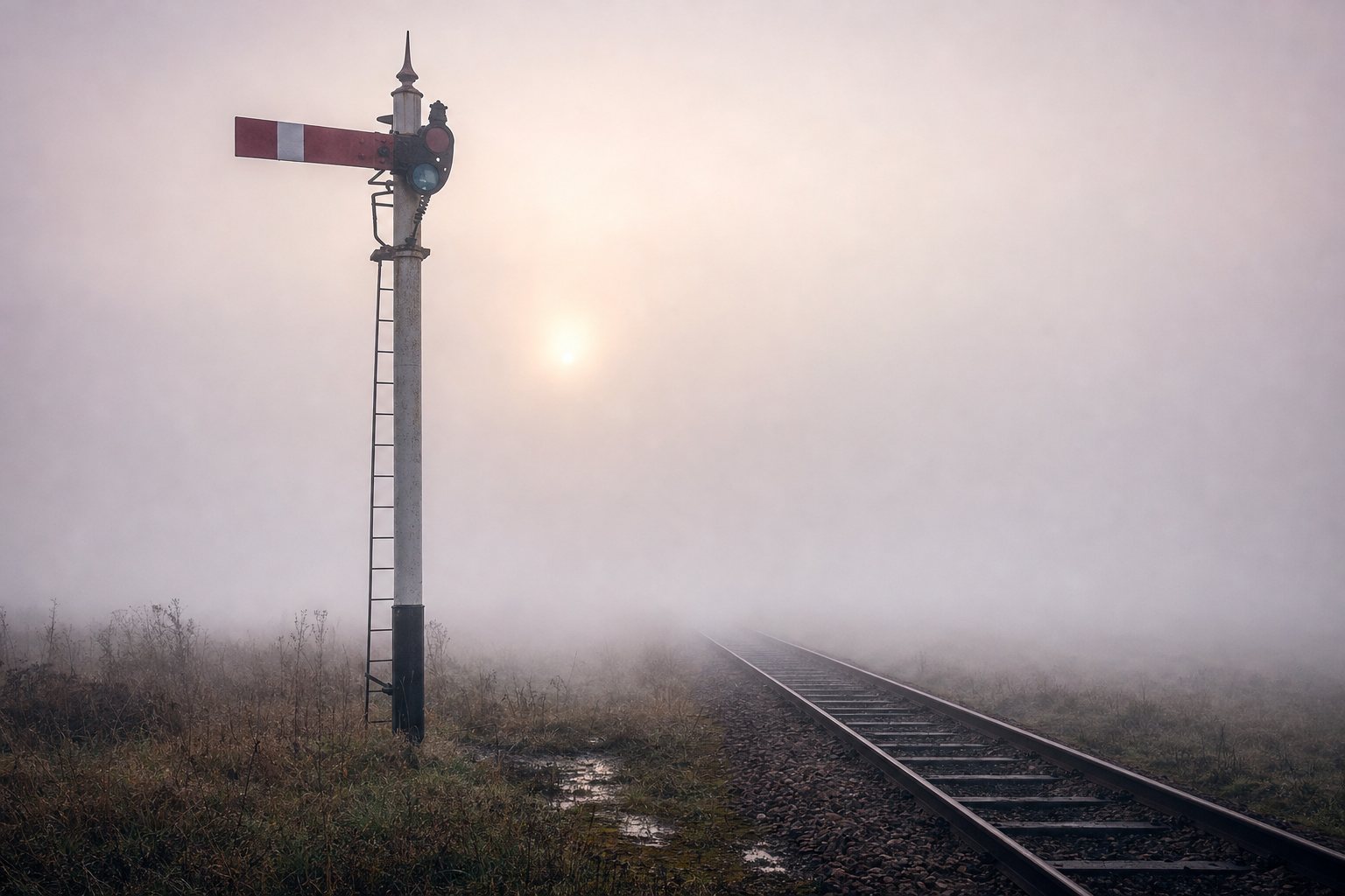
The old enemy Before track circuits, railways posted fogmen at signals to clip detonators to the rail when the arm could not be seen. AI-generated still.
  • Fewer trains per hour on the line
  • More aspects to read at a glance
  • Signals seen for only seconds
Why not just longer blocks?
543 m
past the main signal before stopping: 1,543 − 1,000
At 200 km/h, braking from the distant signal
Chapter IV · Red, yellow, green

The limit of lineside signals

Wikipedia, railway signalling: for average trains at 160 km/h a standard braking distance of 2,000 m is used in UK signalling. Wikipedia, LZB: German distant signals are 1,000 m before the main signal, while a train with strong brakes needs 1,543 m to stop from 200 km/h. Longer blocks would reduce line capacity, and extra aspects would still be hard to see at speed; LZB became mandatory in Germany where trains could exceed 160 km/h, and in Spain above 220 km/h.

Try it: the signals stay 1,000 m apart; at each speed the train brakes at the yellow with 1 m/s² and the model shows where it stops.

The 3D railway is a teaching model: distances are to scale where numbers are given, but trains, signals and cables are drawn larger so they can be seen.

Sources: Wikipedia: railway signalling; Wikipedia: Linienzugbeeinflussung (LZB)

Chapter V · Signals in the cab

Chapter V

Signals in the cab

The line talks to the train.

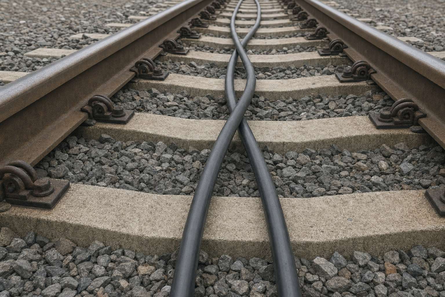
The answer was to move the signal into the cab. Germany's LZB, first shown at two hundred kilometres an hour in 1965, lays two cables between the rails that cross over every hundred metres.

A control centre covering thirty to forty kilometres of line talks to every train through those cables, one to five times a second. Each crossing tells the train exactly where it is.

In the cab, the driver sees the permitted speed and how far the line is clear, up to about thirteen kilometres ahead. Spain chose LZB for its first high-speed line, Madrid to Seville, opened in 1992 for three hundred kilometres an hour.

100 m
between cable crossings
1965
first shown, Munich, at 200 km/h
LZB in numbers
Two cables, crossing Because the cable runs the whole length of the line, the train stays in touch with the centre continuously, not only at fixed points. AI-generated still.
30–40 km
of line per control centre
1–5 ×/s
messages to each train
A conversation, many times a second
4–13.2 km
of line ahead, depending on the equipment
What the driver sees
~480 km
of line
300 km/h
design operation
Madrid–Seville, 1992
Chapter V · Signals in the cab

LZB: the line talks to the train

Wikipedia, LZB (Linienzugbeeinflussung): a cab signalling and train protection system used on selected German and Austrian lines and on the Spanish AVE. Two conductor cables run between the rails and cross every 100 m; at each crossing the signal phase changes by 180°, which helps trains find their position. A control centre covering a 30–40 km segment sends call telegrams to each train one to five times a second and the train replies. The driver can see between 4 and 13.2 km ahead, depending on the equipment. Developed by Deutsche Bundesbahn with Siemens, tested in 1963 and demonstrated in 1965 at the Munich transport exhibition at 200 km/h. The Madrid–Córdoba–Seville line opened in 1992 for 300 km/h operation and is about 480 km long. LZB is due to be replaced by ETCS between 2023 and 2030.

On screen: pulses along the cable stand for the messages between the control centre and the train.

The 3D railway is a teaching model: distances are to scale where numbers are given, but trains, signals and cables are drawn larger so they can be seen.

Sources: Wikipedia: Linienzugbeeinflussung (LZB)

Cab signalling comes with train protection. The computer draws a braking curve, a line on a graph of speed, not a bend in the track: the highest speed at which the train can still stop before the end of the clear track.

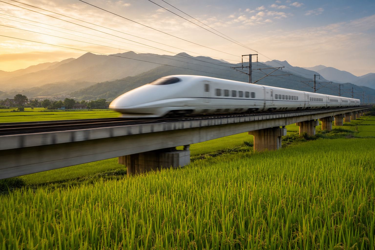
Japan built automatic train control into its bullet trains from the start. Since the first Shinkansen opened on 1 October 1964, it has slowed any train approaching another, and the network has had no derailment or collision that killed a passenger.

The rule is simple: go above the curve, and the system brakes by itself. Try ignoring the curve.

vmax⁡(x)=2a (xend−x)v_{\max}(x) = \sqrt{2a\,(x_{\text{end}} - x)}
xend−xx_{\text{end}} - x
distance left to the end of the clear track
aa
the braking the system can count on
The curve at each point
1 m/s²
the braking the curve counts on; real systems add margins
In this model
A bullet train Japan’s high-speed lines were built with cab signalling from day one. AI-generated still.
1 Oct 1964
opened
0
passenger deaths from derailment or collision since
Tōkaidō Shinkansen
  • Below the curve: the driver drives
  • Near it: a warning in the cab
  • Above it: automatic brakes
Train protection
Chapter V · Signals in the cab

A curve the train may not cross

Wikipedia, railway signalling: a train protection system is overlaid on cab signalling and can apply the brakes automatically if the driver fails to control speed as required. The braking curve shown is the simple constant-deceleration form v = √(2a·d); real systems use more detailed curves with margins. Nippon.com: the Tōkaidō Shinkansen began service on 1 October 1964; its automatic train control slows a train automatically as it nears another train or a stop, train-to-train collisions are essentially impossible and none has occurred, and the full-standard network has had no derailment or collision that caused a passenger fatality.

Try it: “ignore the curve” keeps the throttle open; the protection system takes over the brakes when the speed crosses the curve.

The 3D railway is a teaching model: distances are to scale where numbers are given, but trains, signals and cables are drawn larger so they can be seen.

Sources: Wikipedia: railway signalling; Nippon.com: safety and convenience, how the Shinkansen changed Japan

Chapter VI · Where protection ends

Chapter VI

Where protection ends

A system guards only the track it covers.

Protection only works where it is installed and switched on. On 24 July 2013, near Santiago de Compostela in Spain, a train came off a high-speed stretch built for ERTMS, Europe's newer system that can brake by itself, towards a curve limited to eighty kilometres an hour. The train's own ERTMS had been switched off, a court later heard.

The track before the curve had only an older system called ASFA, which warns about overspeed but does not brake by itself. The train's recorder showed a hundred and seventy-nine kilometres an hour when it derailed. Seventy-nine people died.

In 2024 a court convicted the driver, and the former safety director of Adif, which runs Spain's tracks, of gross negligence. Compare protection that ends before the curve with protection that reaches it.

A curve at the edge of a city Where a high-speed line joins older track, the limits change fast. AI-generated still.
24 July 2013
an Alvia train from Madrid to Ferrol
Angrois, near Santiago de Compostela
Limit on the curve80
Recorded at derailment179
Recorded 250 m before195
Speed at the curve
  • ERTMS: supervises speed and can brake
  • On this train: ERTMS switched off
  • ASFA before the curve: no speed check there
Two systems on one route
2
people convicted of gross negligence
2 y 6 m
prison sentence for each
The verdict, 26 July 2024
Chapter VI · Where protection ends

The gap before the curve

Wikipedia, Santiago de Compostela derailment: on 24 July 2013 at about 20:41, an Alvia train from Madrid to Ferrol derailed on a curve at Angrois limited to 80 km/h. The event recorder showed 195 km/h about 250 m before the curve and 179 km/h when it derailed. The high-speed section had ERTMS, but it had no control to slow the train to the lower limit before the curve; the conventional track carried only ASFA, which warns about overspeed but does not brake automatically, and the investigation examined why ERTMS had been disconnected. elDiario.es, on the trial: the on-board ERTMS was giving problems, so Renfe asked for it to be disconnected and Adif’s Andrés Cortabitarte authorised it; ASFA was working, but checked speed only at certain points, and the approach to the curve was not one of them. The death toll was later given as 79. On 26 July 2024 a court convicted the driver and Adif’s former safety director of gross negligence; each received two years, six months and one day in prison.

Try it: “as in 2013” ends supervision before the curve; “to the curve” extends it. The model only shows the speed reaching the curve; it does not show the derailment.

The 3D railway is a teaching model: distances are to scale where numbers are given, but trains, signals and cables are drawn larger so they can be seen.

Sources: Wikipedia: Santiago de Compostela derailment; elDiario.es: the keys of the Alvia trial, a recognised human error and missing safeguards

Chapter VII · Moving block

Chapter VII

Moving block

A safe zone that travels with the train.

Europe's common answer is ERTMS, and its train-control part, ETCS. Small beacons in the track, called balises, tell each passing train exactly where it is.

A control centre then sends each train, by radio, its movement authority: permission to run up to a given point, and no further.

Lineside signals are then no longer needed. European Union rules require ETCS on the core trans-European network by 2030, and on the wider network by 2040.

The next step is moving block. Instead of fixed sections, each train carries a safe zone that no other train may enter, so trains can run closer together. The hard part is proving the train is still in one piece, so that no carriage has come loose behind it. Switch between fixed and moving block.

30+
national signalling systems ERTMS was made to replace
One standard for Europe
  • Level 1: balises over lineside signals
  • Level 2: radio block centre, no lineside signals needed
  • Level 3: trains report their own position
ETCS levels
  1. 1990s ERTMS development begins
  2. 2030 ETCS on the core network
  3. 2040 ETCS on the comprehensive network
Europe’s deadlines
Level 3
still in trials, including in the Netherlands and Germany
Moving block today
whole blocks
kept free behind each train, fixed
≈ braking distance
plus a margin, moving
Fixed against moving block
Chapter VII · Moving block

ETCS and moving block

Railway News: ERTMS combines ETCS (train protection and speed supervision) with GSM-R radio, to be succeeded by FRMCS, and was created to replace more than 30 national signalling systems. A movement authority is permission to proceed to a given point; Eurobalises in the track give passing trains fixed location data. At Level 2 a radio block centre sends movement authorities continuously and lineside signals are not needed; Level 3 is moving block, with trains reporting their own position and integrity, and is in trials. The revised TEN-T Regulation requires ETCS on the core network by 2030 and the comprehensive network by 2040. RailwaySignalling.eu: Level 1 uses Eurobalises; Level 2 a radio block centre; Level 3 relies on position and integrity information sent from the train. Wikipedia, railway signalling: under moving block, computers calculate a safe zone around each train that no other train may enter, which raises capacity.

Try it: in fixed block the following train must stop at the end of a whole free block; in moving block it follows a safe zone that travels with the front train.

The 3D railway is a teaching model: distances are to scale where numbers are given, but trains, signals and cables are drawn larger so they can be seen.

Sources: Railway News: what is ERTMS? The European Rail Traffic Management System explained; RailwaySignalling.eu: ETCS levels, how do they work?; Wikipedia: railway signalling

Epilogue

Epilogue

The track ahead must be known to be clear

Every signal answers one question.

From stopwatches to radio, many steps in signalling came after a disaster showed what the last system could not see. The goal never changed: one train, and one stretch of empty track ahead of it.

Yet every system keeps a way for people to move trains when equipment fails, and those orders are a human link again. At Urda, investigators must establish how a train came to be sent onto occupied track, and why the safeguards did not stop it.

  1. 1861 Clayton Tunnel: time is not enough
  2. 1872 Fail-safe track circuit
  3. 1889 Armagh: block, interlocking, brakes by law
  4. 1964 Shinkansen with automatic train control
  5. 1992 Madrid–Seville opens with LZB
  6. 2013 Santiago: a gap in protection
  7. 2030 ETCS due on Europe’s core network
How signalling grew
No train moves until the line ahead is known to be clear.The principle behind every system in this film
  • Why the front train had stopped
  • Why the second train was authorised
  • What the protection systems did
Open questions at Urda
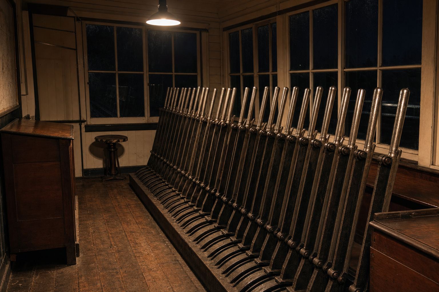
Levers that lock each other The frame under the floor locks the levers against one another, so no signal can be cleared for a route that is not set. AI-generated still.
CIAF
Spain’s railway accident investigation commission
Who answers
Epilogue

Sources and notes

Every figure in this film comes from the sources below, which were read for it. The account of the Urda collision is limited to what officials said on 28 October 2026; the cause is for the railway accident investigation commission (CIAF) to establish, and nothing here should be taken as a finding. Braking figures are indicative values for dry, level track, and the 3D railway is a simplified teaching model. All stills are AI-generated illustrations, not photographs of real places or events.

Sources: ABC News (28 Oct 2026): train collision on a high-speed line in Spain kills at least 68; CBS News (28 Oct 2026): high-speed train accident in Spain near Urda; Railway News (Oct 2026): Spain train crash near Urda, Renfe and Iryo, what is known; Demócrata, citing Europa Press (Oct 2026): the Guardia Civil questions the Adif operator who authorised the AVE before the Urda accident; Railway News: train braking distance, how long does a train take to stop?; Wikipedia: railway signalling; Wikipedia: Clayton Tunnel rail crash; Wikipedia: track circuit; Wikipedia: William Robinson (inventor); Wikipedia: Armagh rail disaster; Wikipedia: Linienzugbeeinflussung (LZB); Nippon.com: safety and convenience, how the Shinkansen changed Japan; Wikipedia: Santiago de Compostela derailment; elDiario.es: the keys of the Alvia trial, a recognised human error and missing safeguards; Railway News: what is ERTMS? The European Rail Traffic Management System explained; RailwaySignalling.eu: ETCS levels, how do they work?